Private
Public Access

68 lines
4.6 KiB
XML
68 lines
4.6 KiB
XML
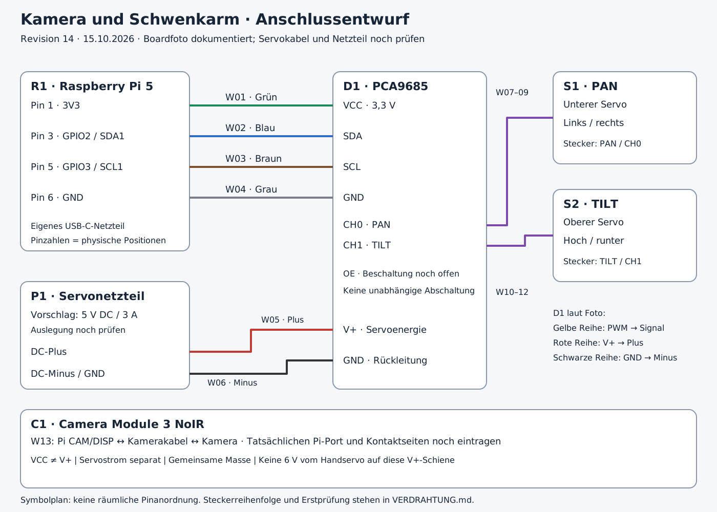


<svg xmlns="http://www.w3.org/2000/svg" width="1400" height="1000" viewBox="0 0 1400 1000">
|
||
<rect width="1400" height="1000" fill="#f5f7fa"/>
|
||
<style>text{font-family:DejaVu Sans,Arial,sans-serif;fill:#172536;font-size:18px}.title{font-size:30px;font-weight:bold}.head{font-size:22px;font-weight:bold}.small{font-size:16px}.wire{fill:none;stroke-width:4;stroke-linejoin:round}</style>
|
||
<text x="40" y="48" class="title">Kamera und Schwenkarm · Anschlussentwurf</text>
|
||
<text x="40" y="82" class="">Revision 14 · 15.10.2026 · Boardfoto dokumentiert; Servokabel und Netzteil noch prüfen</text>
|
||
<rect x="40" y="140" width="330" height="350" rx="14" fill="white" stroke="#8796a8" stroke-width="2"/>
|
||
<text x="60" y="176" class="head">R1 · Raspberry Pi 5</text>
|
||
<text x="60" y="212" class="">Pin 1 · 3V3</text>
|
||
<text x="60" y="272" class="">Pin 3 · GPIO2 / SDA1</text>
|
||
<text x="60" y="332" class="">Pin 5 · GPIO3 / SCL1</text>
|
||
<text x="60" y="392" class="">Pin 6 · GND</text>
|
||
<text x="60" y="447" class="small">Eigenes USB-C-Netzteil</text>
|
||
<text x="60" y="475" class="small">Pinzahlen = physische Positionen</text>
|
||
<rect x="650" y="140" width="300" height="620" rx="14" fill="white" stroke="#8796a8" stroke-width="2"/>
|
||
<text x="670" y="176" class="head">D1 · PCA9685</text>
|
||
<polyline class="wire" points="370,206 650,206" stroke="#20885c"/>
|
||
<text x="440" y="196" class="">W01 · Grün</text>
|
||
<text x="670" y="212" class="">VCC · 3,3 V</text>
|
||
<polyline class="wire" points="370,266 650,266" stroke="#316dc8"/>
|
||
<text x="440" y="256" class="">W02 · Blau</text>
|
||
<text x="670" y="272" class="">SDA</text>
|
||
<polyline class="wire" points="370,326 650,326" stroke="#80502e"/>
|
||
<text x="440" y="316" class="">W03 · Braun</text>
|
||
<text x="670" y="332" class="">SCL</text>
|
||
<polyline class="wire" points="370,386 650,386" stroke="#7a7f87"/>
|
||
<text x="440" y="376" class="">W04 · Grau</text>
|
||
<text x="670" y="392" class="">GND</text>
|
||
<text x="670" y="445" class="">CH0 · PAN</text>
|
||
<text x="670" y="485" class="">CH1 · TILT</text>
|
||
<text x="670" y="540" class="small">OE · Beschaltung noch offen</text>
|
||
<text x="670" y="573" class="small">Keine unabhängige Abschaltung</text>
|
||
<text x="670" y="650" class="">V+ · Servoenergie</text>
|
||
<text x="670" y="710" class="">GND · Rückleitung</text>
|
||
<rect x="1080" y="140" width="280" height="180" rx="14" fill="white" stroke="#8796a8" stroke-width="2"/>
|
||
<text x="1100" y="176" class="head">S1 · PAN</text>
|
||
<text x="1100" y="210" class="">Unterer Servo</text>
|
||
<text x="1100" y="246" class="">Links / rechts</text>
|
||
<text x="1100" y="286" class="small">Stecker: PAN / CH0</text>
|
||
<rect x="1080" y="370" width="280" height="180" rx="14" fill="white" stroke="#8796a8" stroke-width="2"/>
|
||
<text x="1100" y="406" class="head">S2 · TILT</text>
|
||
<text x="1100" y="440" class="">Oberer Servo</text>
|
||
<text x="1100" y="476" class="">Hoch / runter</text>
|
||
<text x="1100" y="516" class="small">Stecker: TILT / CH1</text>
|
||
<polyline class="wire" points="950,440 990,440 990,230 1080,230" stroke="#7b4ba7"/>
|
||
<text x="968" y="186" class="small">W07–09</text>
|
||
<polyline class="wire" points="950,480 1025,480 1025,460 1080,460" stroke="#7b4ba7"/>
|
||
<text x="968" y="576" class="small">W10–12</text>
|
||
<text x="1080" y="617" class="small">D1 laut Foto:</text>
|
||
<text x="1080" y="646" class="small">Gelbe Reihe: PWM → Signal</text>
|
||
<text x="1080" y="675" class="small">Rote Reihe: V+ → Plus</text>
|
||
<text x="1080" y="704" class="small">Schwarze Reihe: GND → Minus</text>
|
||
<rect x="40" y="550" width="330" height="210" rx="14" fill="white" stroke="#8796a8" stroke-width="2"/>
|
||
<text x="60" y="586" class="head">P1 · Servonetzteil</text>
|
||
<text x="60" y="621" class="">Vorschlag: 5 V DC / 3 A</text>
|
||
<text x="60" y="650" class="small">Auslegung noch prüfen</text>
|
||
<text x="60" y="693" class="">DC-Plus</text>
|
||
<text x="60" y="736" class="">DC-Minus / GND</text>
|
||
<polyline class="wire" points="370,687 490,687 490,644 650,644" stroke="#c13b35"/>
|
||
<text x="510" y="630" class="small">W05 · Plus</text>
|
||
<polyline class="wire" points="370,730 560,730 560,704 650,704" stroke="#333333"/>
|
||
<text x="405" y="753" class="small">W06 · Minus</text>
|
||
<rect x="40" y="800" width="1320" height="153" rx="14" fill="white" stroke="#8796a8" stroke-width="2"/>
|
||
<text x="60" y="836" class="head">C1 · Camera Module 3 NoIR</text>
|
||
<text x="60" y="868" class="">W13: Pi CAM/DISP ↔ Kamerakabel ↔ Kamera · Tatsächlichen Pi-Port und Kontaktseiten noch eintragen</text>
|
||
<text x="60" y="904" class="small">VCC ≠ V+ | Servostrom separat | Gemeinsame Masse | Keine 6 V vom Handservo auf diese V+-Schiene</text>
|
||
<text x="40" y="982" class="small">Symbolplan: keine räumliche Pinanordnung. Steckerreihenfolge und Erstprüfung stehen in VERDRAHTUNG.md.</text>
|
||
</svg>
|